Stainless steel concentric reducers are fittings used to connect two pipes of different diameters. Their primary function is to alter the pipe diameter and flow velocity, ensuring smooth fluid flow within the piping system.
What is a concentric reducer?
The primary structural feature of a concentric reducer is its concentric design. This structure ensures that the flow direction of the fluid remains unchanged as it passes through the reducer, maintaining a relatively stable flow state. The characteristic of a concentric reducer lies in the fact that the centerlines of its two ends (the larger and smaller openings) are perfectly aligned. When viewed from the side, it exhibits a symmetrical conical structure, resembling a bell or funnel. This design ensures smooth fluid transition within the pipeline, minimizing the generation of vortices and turbulence, making it particularly suitable for applications with stringent requirements for fluid flow.
Differences Between Concentric and Eccentric Reducers
The primary difference between concentric reducers and eccentric reducers lies in the position of the centerlines at both ends: the centerlines of a concentric reducer are aligned on the same straight line, forming a symmetrical conical shape, suitable for vertical pipes or applications requiring high fluid symmetry; whereas the centerlines of an eccentric reducer are not aligned on the same straight line, with one side transitioning in a straight line, commonly used in horizontal pipes to prevent gas accumulation or liquid stagnation.
Concentric Reducer Specification
| Size Range | 3/4″ – 60″ / DN20 – 1500 |
| Thickness Schedule | SCH 10 – SCH 80, SCH 160, XXS |
| America Standard | ANSI / ASME B16.9 |
| Japan Standard | JIS B2311/2312/2313 |
| Germany Standard | DIN2605/2615/2616/2617 |
| Europe Standard | EN10253 |
| Stainless Steel | ASTM A403 WP304/304L/304H, 316/316L, 310S, 317,347,904L |
Features of Stainless Steel Concentric Reducers
High Corrosion Resistance: The composition of stainless steel makes it resistant to corrosion from a wide range of chemical media, making it ideal for use in industries such as the chemical, petroleum, and food processing.
Hygienic and Non-Toxic: The smooth surface resists bacterial growth and is easy to clean, meeting food-grade and sanitary standards.
High Strength and Durability: Withstands high pressures and temperatures for a long service life.
Excellent Weldability: Easily welds to stainless steel pipes, creating a tightly sealed piping system.
Concentric Reducer Weight Calculation Formula
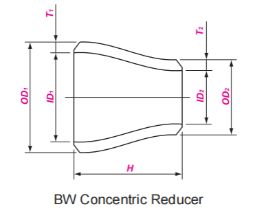
The steel pipe reducer weight formula is 0.02466 * S <(D+d)/2 – S> * H / 1000
D = Large end diameter in mm.
d = Small end diameter in mm.
S = Large end Thickness in mm.
H = Height from end to end.
If we want to calculate the weight by formula, we need to know above 4 factors. Where can you get them? Usually we get the them from pipe reducer dimensions.
ASME B16.9 Concentric Reducer Dimension
| OD1 | OD2 | END TO END | SCH 40 WEIGHT |
| NPS | NPS | H | KG |
| 3/4 | 3/8 – 1/2 | 38 | 0.07 |
| 1 | 1/2 – 3/4 | 51 | 0.14 |
| 1 1/4 | 1/2 – 1 | 51 | 0.19 |
| 1 1/2 | 1/2 – 1 1/4 | 64 | 0.29 |
| 2 | 3/4 – 1 1/2 | 76 | 0.46 |
| 2 1/2 | 1 – 2 | 89 | 0.85 |
| 3 | 1 1/4 – 2 1/2 | 102 | 1.11 |
| 4 | 2 – 3 1/2 | 102 | 1.8 |
| 5 | 2 – 4 | 127 | 3.05 |
| 6 | 2 1/2 – 5 | 140 | 4.35 |
| 8 | 3 1/2 – 6 | 152 | 7.12 |
| 10 | 4 – 8 | 178 | 11.8 |
| 12 | 5 – 10 | 203 | 17.8 |
| 14 | 6 – 12 | 330 | 34.3 |
| 16 | 6 – 14 | 356 | 48.3 |
| 18 | 8 – 16 | 381 | 65.3 |
| 20 | 10 – 18 | 508 | 102 |
| 22 | 12 – 20 | 508 | – |
| 24 | 12 – 22 | 508 | 143 |
| 26 | 12 – 24 | 610 | – |
| 28 | 14 – 26 | 610 | – |
| 30 | 14 – 28 | 610 | – |
| 32 | 20 – 30 | 610 | 230 |
| 34 | 22 – 32 | 610 | 245 |
| 36 | 22 – 34 | 610 | 282 |
| 38 | 24 – 36 | 610 | – |
| 40 | 28 – 38 | 610 | – |
| 42 | 28 – 40 | 610 | – |
| 44 | 32 – 42 | 610 | – |
| 46 | 34 – 44 | 711 | – |
| 48 | 36 – 46 | 711 | – |
| 52 | 40 – 48 | 711 | – |
| 56 | 40 – 52 | 711 | – |
| 60 | 44 – 56 | 711 |
ASME B16.9 Concentric Reducer Weight
| Concentric Reducer Weight Chart | |||||||||
| DN | NPS | 10S | 20 | STD | 40 | XS | 80 | 160 | XXS |
| 20 | 3/4 | 0.1 | / | 0.1 | 0.1 | 0.1 | 0.1 | / | / |
| 25 | 1 | 0.1 | / | 0.2 | 0.2 | 0.2 | 0.2 | / | / |
| 32 | 1 1/4 | 0.1 | / | 0.2 | 0.2 | 0.3 | 0.3 | 0.2 | / |
| 40 | 1 1/2 | 0.2 | / | 0.3 | 0.3 | 0.4 | 0.4 | / | / |
| 50 | 2 | 0.3 | / | 0.4 | 0.4 | 0.6 | 0.6 | 0.6 | 1 |
| 65 | 2 1/2 | 0.5 | / | 0.8 | 0.8 | 1.0 | 1.0 | 1.0 | / |
| 80 | 3 | 0.6 | / | 1.1 | 1.1 | 1.4 | 1.4 | 1.7 | 1 |
| 90 | 3 1/2 | 0.7 | / | 1.4 | 1.4 | 1.9 | 1.9 | / | / |
| 100 | 4 | 0.8 | / | 1.6 | 1.6 | 2.3 | 2.3 | 2.4 | / |
| 125 | 5 | 1.4 | / | 2.81 | 2.8 | 4.0 | 3.9 | 4.4 | / |
| 150 | 6 | 1.9 | / | 4.0 | 4.0 | 6.0 | 6.0 | 7.1 | 8.6 |
| 200 | 8 | 2.8 | / | 6.3 | 6.3 | 6.0 | 9.3 | 10.8 | 12.6 |
| 250 | 10 | 4.6 | 7.9 | 10.7 | 10.7 | 9.3 | 17.5 | 18.4 | 17.9 |
| 300 | 12 | 7.0 | 11.2 | 15.8 | 16.3 | 14.5 | 25.1 | 32.5 | 29.3 |
| 350 | 14 | 14.0 | 25.6 | 28.8 | 32.1 | 21.0 | 56.5 | 53.3 | 41.7 |
| 400 | 16 | 17.5 | 30.5 | 38.5 | 48.8 | 37.1 | 79 | 106.0 | / |
| 450 | 18 | 21.5 | 35.2 | 44.5 | 64.3 | 48.8 | 102 | 143.0 | / |
| 500 | 20 | 36.0 | 62.7 | 62.7 | 98.5 | 58.5 | 165 | / | / |
| 550 | 22 | 38.0 | 72.6 | 72.6 | / | 80.4 | 181 | / | / |
| 600 | 24 | 47.5 | 97.0 | 79.1 | 142.0 | 93.8 | 226 | / | / |
Stainless Steel Concentric Reducer Manufacturing Process:
1. Hot Rolling (Extruded Seamless Steel Tubing): Round tube blank → Heating → Piercing → Three-roll oblique rolling, continuous rolling, or extrusion → De-burring → Sizing (or reducing diameter) → Cooling → Straightening → Hydrostatic testing (or non-destructive testing) → Marking → Storage
Hot rolling is a processing method performed above the recrystallization temperature of the metal material. For stainless steel, this typically means temperatures exceeding 1000°C. The stainless steel tube blank is heated to high temperatures and then repeatedly rolled through rollers to reduce its diameter and thin its wall thickness, ultimately forming the desired-sized tubing.
2. Cold drawing (rolling) seamless steel tubes: Round tube blank → Heating → Piercing → Heading → Annealing → Acid washing → Oil coating (copper plating) → Multiple cold drawing (cold rolling) → Blank tube → Heat treatment → Straightening → Hydrostatic testing (inspection) → Marking → Storage.
Cold drawing is performed below the recrystallization temperature, typically at room temperature. Using hot-rolled tubes as raw material, the tubes are drawn through a die to further reduce their diameter and wall thickness. To ensure smooth drawing operations, annealing is typically performed between drawing intervals.
How to make a reducer?
Reducers are pipe fittings designed to meet pipe diameter requirements. Common forming processes include reducing/expanding, or both. Stamping can also be used for certain reducer sizes.
a. Reducing/Expanding Forming
The reducing/expanding forming process involves placing a tube blank of the same diameter as the larger end of the reducer into a die. Pressing is performed along the tube blank’s axial direction, causing the metal to move along the die cavity and shrink. Depending on the size of the reduced diameter, this process can be performed in a single press or multiple presses.
b. Stamping
In addition to using steel pipe as raw material to produce reducers, some sizes can also be produced using steel plate using a stamping process. The die used for drawing is designed based on the reducer’s inner surface dimensions. The blanked steel plate is then stamped and stretched using the die.
Common Applications
Chemical and petrochemical industries
Food and beverage processing
Pharmaceutical industry
Water treatment and desalination
Oil and gas transportation
Pulp and paper and sugar industries
Marine and offshore engineering