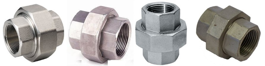
In piping systems, the union is one of the commonly used forged pipe fittings, primarily employed at pipeline locations requiring frequent disassembly, inspection, and maintenance. Knowing the MSS SP-83 union dimensions can help engineers accurately select and install them.A union consists of three parts: a pair of fittings with internal threads or socket weld ends, and an intermediate threaded ring, making installation and removal highly convenient. MSS SP-83 is an internationally adopted standard for union fittings, covering both socket weld and threaded connection configurations.
What is a union?
A union, also known as a union joint, is a component used for removable connections between pipes. It typically consists of three parts: a male end, a female end, and a gasket. The male and female ends are connected to the two pipes to be joined, achieving a tight seal through threaded connections, while the gasket serves as a seal to prevent leakage of the medium inside the pipes.
Compared to traditional welding or flange connections, the most significant feature of union is their removability. This feature makes pipeline installation, maintenance, and replacement more convenient, eliminating the need for destructive operations on the pipeline, significantly improving work efficiency, and reducing maintenance costs.
MSS SP-83 Pipe Union Specification
| Size: | 1/8″ to 3″ / DN6 to DN80 |
| Pressure: | 3000 LB,6000LB |
| Connection: | Socket Weld and Threaded Union |
| Thread Type: | Female and Male NPT, BSPP and BSPT |
| Alloy Steel: | ASTM A182 F1, F5, F9, F11, F12, F22, F91 |
| Carbon Steel: | ASTM A105, A350 LF2/LF3, A694 F52, F60, F65, F70 |
| Stainless Steel: | ASTM A182 F304, F316, F317, F310, F321 |
| Duplex Stainless Steel: | ASTM A182 F51, F53, F55 |
ZIZI offered range of MSS SP-83 Union Pipe Fittings is intended and developed in accordance with the international quality standards at our infrastructure facility to achieve the very best benchmarks of quality. Our modernized infrastructure is crowned by means of recent tools and advanced machines that enable us to satisfy the large demands of customers in a dexterous manner. Our products are can further be made-to-order as per the detailed requirements given by our valuable Client..
Types of Unions
Socket Weld Union:
Socket welding involves inserting a steel pipe into a socket hole for welding, hence the term socket weld union. A socket coupling consists of a socket, a spigot, and a socket groove, with the distinctive feature of a socket groove on the spigot, and the spigot and socket located at opposite ends. Socket unions can be widely applied to pipes of various diameters and are also suitable for water meters and valves. Due to the socket structure, pipe joints reduce costs and offer extremely convenient installation, use, and maintenance, while also providing excellent leak prevention capabilities, making them highly promising in the market.
Threaded connections involve screwing steel pipes into threaded holes for connection, hence the term threaded union.Threaded unions are the most common type of joint, characterized by using a threaded connection method for pipe connections. They primarily consist of three parts: a male end with external threads, a female end with internal threads, and a nut. By rotating the nut, the sealing surfaces of the male and female ends can be tightly aligned, thereby achieving connection and sealing. Thread forms can include BSP, NPT, G, etc., and the connection is further secured using a locking nut and a seal ring. Suitable for small-diameter pipes, threaded connections achieve pipe sealing. They are easy to install and commonly used in water pipes, gas pipes, and other applications.
MSS SP-83 Union Dimension and Weight
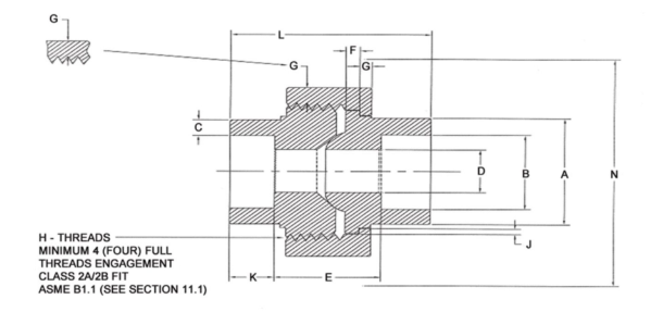
Class 3000 Socket Weld Union Dimension
Dimensions in inches

| NPS | Pipe End (min.) | Socket Bore Dia. | Socket Wall (min.) | Water Way Bore(a) | Laying Length | Male Flange (min.) | Nut (min.) | Threads per Inch | Bearing (min.) | Depth of Socket (min.) | Length of Assy. (nominal) | Clear Assy. Nut |
| A | B | C | D | E | F | G | H | J | K | L | N | |
| 1/8 | 0.86 | 0.440 0.420 | 0.125 | 0.299 0.239 | 0.88 0.75 | 0.125 | 0.125 | 16 | 0.049 | 0.38 | 1.63 | 2.0 |
| 1/4 | 0.86 | 0.575 0.555 | 0.130 | 0.394 0.334 | 0.88 0.75 | 0.125 | 0.125 | 16 | 0.049 | 0.38 | 1.63 | 2.0 |
| 3/8 | 1.02 | 0.710 0.690 | 0.138 | 0.523 0.463 | 1.06 0.81 | 0.135 | 0.135 | 14 | 0.054 | 0.38 | 1.81 | 2.2 |
| 1/2 | 1.23 | 0.875 0.855 | 0.161 | 0.652 0.592 | 1.06 0.81 | 0.145 | 0.145 | 14 | 0.059 | 0.38 | 1.93 | 2.3 |
| 3/4 | 1.46 | 1.085 1.065 | 0.168 | 0.854 0.794 | 1.25 1.00 | 0.160 | 0.160 | 11 | 0.066 | 0.50 | 2.24 | 2.6 |
| 1 | 1.79 | 1.350 1.330 | 0.196 | 1.079 1.019 | 1.35 1.03 | 0.180 | 0.175 | 11 | 0.073 | 0.50 | 2.44 | 3.1 |
| 1 1/4 | 2.16 | 1.695 1.675 | 0.208 | 1.410 1.350 | 1.60 1.28 | 0.210 | 0.205 | 10 | 0.084 | 0.50 | 2.80 | 3.7 |
| 1/1 | 2.42 | 1.935 1.915 | 0.218 | 1.640 1.580 | 1.66 1.34 | 0.230 | 0.220 | 10 | 0.091 | 0.50 | 3.01 | 4.4 |
| 2 | 2.96 | 2.426 2.406 | 0.238 | 2.097 2.037 | 1.79 1.47 | 0.260 | 0.250 | 10 | 0.106 | 0.62 | 3.39 | 5.2 |
| 2 1/2 | 3.61 | 2.931 2.906 | 0.302 | 2.529 2.409 | 2.43 2.05 | 0.295 | 0.280 | 8 | 0.121 | 0.62 | 4.03 | 5.9 |
| 3 | 4.30 | 3.560 3.535 | 0.327 | 3.128 3.008 | 2.51 2.11 | 0.325 | 0.315 | 8 | 0.139 | 0.62 | 4.29 | 6.9 |
| NOTE: (a)The contact diameter of the male/female end is affected by the waterway bore(Col.D).The manufacturer shall consider the relationships between the contact point and waterway diameter in his design. | ||||||||||||
Class 6000 Socket Weld Union Dimension
Dimensions in inches
| NPS | Pipe End (min.) | Socket Bore Dia. | Socket Wall (min.) | Water Way Bore(a) | Laying Length | Male Flange (min.) | Nut (min.) | Threads per Inch | Bearing (min.) | Depth of Socket (min.) | Length of Assy. (nominal) | Clear Assy. Nut |
| A | B | C | D | E | F | G | H | J | K | L | N | |
| 1/8 | 0.86 | 0.440 0.420 | 0.135 | 0.189 0.126 | 0.88 0.75 | 0.125 | 0.125 | 16 | 0.049 | 0.38 | 1.63 | 2.0 |
| 1/4 | 1.02 | 0.575 0.555 | 0.158 | 0.280 0.220 | 1.06 0.81 | 0.135 | 0.135 | 14 | 0.054 | 0.38 | 1.81 | 2.2 |
| 3/8 | 1.23 | 0.710 0.690 | 0.172 | 0.389 0.329 | 1.06 0.81 | 0.145 | 0.145 | 14 | 0.059 | 0.38 | 1.93 | 2.3 |
| 1/2 | 1.46 | 0.875 0.855 | 0.204 | 0.494 0.434 | 1.25 1.00 | 0.160 | 0.160 | 11 | 0.066 | 0.38 | 2.24 | 2.6 |
| 3/4 | 1.79 | 1.085 1.065 | 0.238 | 0.642 0.582 | 1.35 1.03 | 0.180 | 0.175 | 11 | 0.073 | 0.50 | 2.44 | 3.1 |
| 1 | 2.16 | 1.350 1.330 | 0.273 | 0.845 0.785 | 1.60 1.28 | 0.210 | 0.205 | 10 | 0.084 | 0.50 | 2.80 | 3.7 |
| 1 1/4 | 2.42 | 1.695 1.675 | 0.273 | 1.190 1.130 | 1.66 1.34 | 0.230 | 0.220 | 10 | 0.091 | 0.50 | 3.01 | 4.4 |
| 1/1 | 2.96 | 1.935 1.915 | 0.307 | 1.368 1.308 | 1.79 1.47 | 0.260 | 0.250 | 10 | 0.106 | 0.50 | 3.39 | 5.2 |
| 2 | 3.61 | 2.426 2.406 | 0.374 | 1.717 1.657 | 2.43 2.05 | 0.295 | 0.280 | 8 | 0.121 | 0.62 | 4.03 | 5.9 |
| 2 1/2 | 4.30 | 2.931 2.906 | 0.409 | 2.155 2.095 | 2.51 2.11 | 0.325 | 0.315 | 8 | 0.139 | 0.62 | 4.29 | 6.9 |
| NOTE:(a)The contact diameter of the male/female end is affected by the waterway bore(Col.D).The manufacturer shall consider the relationships between the contact point and waterway diameter in his design. | ||||||||||||
CLASS 3000 Threaded Union Dimensions
Dimensions in inches
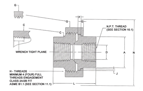
| NPS | Pipe End (min.) | Wall (min.) | Water Way Bore(②) | Male Flange (min.) | Nut (min.) | Threads per Inch | Bearing (min.) | Length of Assy. (nominal) | Clear Assy. Nut |
| A | C | D | F | G | H | J | L | N | |
| 1/8 | 0.58 | 0.095 | 0.332 0.253 | 0.125 | 0.125 | 16 | 0.049 | 1.63 | 2.0 |
| 1/4 | 0.75 | 0.119 | 0.438 0.372 | 0.125 | 0.125 | 16 | 0.049 | 1.63 | 2.0 |
| 3/8 | 0.90 | 0.126 | 0.562 0.532 | 0.135 | 0.135 | 14 | 0.054 | 1.81 | 2.2 |
| 1/2 | 1.09 | 0.147 | 0.703 0.672 | 0.145 | 0.145 | 14 | 0.059 | 1.93 | 2.3 |
| 3/4 | 1.32 | 0.154 | 0.906 0.842 | 0.160 | 0.160 | 11 | 0.066 | 2.24 | 2.6 |
| 1 | 1.63 | 0.179 | 1.141 1.092 | 0.180 | 0.175 | 11 | 0.073 | 2.44 | 3.1 |
| 1 1/4 | 1.99 | 0.191 | 1.484 1.392 | 0.210 | 0.205 | 10 | 0.084 | 2.80 | 3.7 |
| 1/1 | 2.25 | 0.200 | 1.714 1.622 | 0.230 | 0.220 | 10 | 0.091 | 3.01 | 4.4 |
| 2 | 2.76 | 0.218 | 2.188 2.052 | 0.260 | 0.250 | 10 | 0.106 | 3.39 | 5.2 |
| 2 1/2 | 3.36 | 0.276 | 2.609 2.532 | 0.295 | 0.280 | 8 | 0.121 | 4.03 | 5.9 |
| 3 | 4.03 | 0.300 | 3.250 3.042 | 0.325 | 0.315 | 8 | 0.139 | 4.29 | 6.9 |
| NOTE:(a)The contact diameter of the male/female end is affected by the waterway bore(Col.D).The manufacturer shall consider the relationships between the contact point and waterway diameter in his design. | |||||||||
CLASS 6000 Threaded Union Dimensions
Dimensions in inches
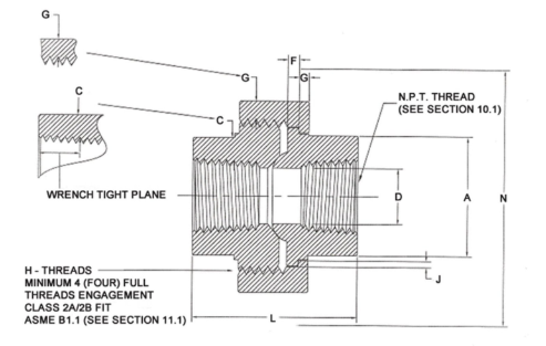
| NPS | Pipe End (min.) | Wall (min.) | Water Way Bore(a) | Male Flange (min.) | Nut (min.) | Threads per Inch | Bearing (min.) | Length of Assy. (nominal) | Clear Assy. Nut |
| A | C | D | F | G | H | J | L | N | |
| 1/8 | 0.65 | 0.124 | 0.332 0.126 | 0.125 | 0.125 | 16 | 0.049 | 1.63 | 2.0 |
| 1/4 | 0.83 | 0.145 | 0.438 0.220 | 0.135 | 0.135 | 14 | 0.054 | 1.81 | 2.2 |
| 3/8 | 0.99 | 0.158 | 0.562 0.329 | 0.145 | 0.145 | 14 | 0.059 | 1.93 | 2.3 |
| 1/2 | 1.22 | 0.188 | 0.703 0.434 | 0.160 | 0.160 | 11 | 0.066 | 2.24 | 2.6 |
| 3/4 | 1.49 | 0.219 | 0.906 0.582 | 0.180 | 0.175 | 11 | 0.073 | 2.44 | 3.1 |
| 1 | 1.82 | 0.250 | 1.141 0.785 | 0.210 | 0.205 | 10 | 0.084 | 2.80 | 3.7 |
| 1 1/4 | 2.16 | 0.250 | 1.484 1.130 | 0.230 | 0.220 | 10 | 0.091 | 3.01 | 4.4 |
| 1/1 | 2.46 | 0.281 | 1.714 1.308 | 0.260 | 0.250 | 10 | 0.106 | 3.39 | 5.2 |
| 2 | 3.06 | 0.344 | 2.188 1.657 | 0.295 | 0.280 | 8 | 0.121 | 4.03 | 5.9 |
| 2 1/2 | 3.63 | 0.375 | 2.609 2.095 | 0.325 | 0.315 | 8 | 0.139 | 4.29 | 6.9 |
| 3 | 4.38 | 0.438 | 3.250 2.594 | 0.401 | 0.401 | 8 | 0.160 | 7.50 | 7.9 |
Weight List
| NOMINAL SZIE | WEIGHT | |
| DN | NPS | 3000 |
| 6 | 1/8 | 0.25 |
| 8 | 1/4 | 0.3 |
| 10 | 3/8 | 0.35 |
| 15 | 3/4 | 0.46 |
| 20 | 1/2 | 0.61 |
| 25 | 1 | 0.85 |
| 32 | 1-1/4 | 1.35 |
| 40 | 1-1/2 | 2.85 |
| 50 | 2 | 4 |
| 65 | 2-1/2 | 4.9 |
| 80 | 3 | 7.1 |
SW & THD Union volume
| Nominal Size | Approximate weight kg | Approximate volume m3 | Nominal Size | Approximate weight kg | Approximate volume m3 | ||
| DN | NPS | DN | NPS | ||||
| 6 | 1/8 | 0.25 | 0.070*10-3 | 32 | 1-1/4 | 1.35 | 0.375*10-3 |
| 8 | 1/4 | 0.30 | 0.070*10-3 | 40 | 1-1/2 | 1.92 | 0.520*10-3 |
| 10 | 3/8 | 0.35 | 0.098*10-3 | 50 | 2 | 2.85 | 0.740*10-3 |
| 15 | 1/2 | 0.46 | 0.125*10-3 | 65 | 2-1/2 | 4.90 | 1.17*10-3 |
| 20 | 3/4 | 0.61 | 0.220*10-3 | 80 | 3 | 7.10 | 1.53*10-3 |
| 25 | 1 | 0.85 | 0.280*10-3 | – | – | – | – |
If you want to know more about the weight and volume of forged pipe fittings, please click on the following keywords
- ASME B16.11 Socket Weld Fitting Weight and Volume Chart
- ASME B16.11 Threaded Fitting Weight and Volume Chart
Union Pipe Fittings Applications
Water treatment systems
Petrochemical pipelines
Heating, ventilation, and air conditioning (HVAC) systems
Pharmaceutical and food industry piping
Laboratory and research piping systems