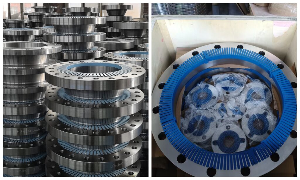
ASME B16.47 Series A Flanges are a standard for large-diameter steel pipe flanges established by the American Society of Mechanical Engineers (ASME). They are primarily applicable to weld neck flanges and blind flanges with nominal diameters ranging from NPS 26 to NPS 60 (approximately DN 650 to DN 1500). This standard specifies detailed requirements for flange design, dimensions, materials, pressure-temperature ratings, and other aspects, aiming to ensure the safety, reliability, and interchangeability of pipeline system connections.
ZIZI specializes in flange production, with products meeting various international and domestic standards, including ASME, DIN, EN, BS, JIS, and GB. We offer a comprehensive range of specifications, from small to large diameters, including weld neck flanges, slip-on flanges, threaded flanges, socket weld flanges, blind flanges, and lap joint flanges. We utilize advanced forging, machining, heat treatment, and surface treatment equipment, along with comprehensive testing methods, including dimensional inspection, spectral analysis, ultrasonic testing, and pressure testing, to ensure that every product meets standard requirements.
Main contents of the ASME B16.47 standard:
1. Pressure-temperature ratings: The standard lists the applicable temperature ranges for flanges under different pressure ratings, ensuring the safety and reliability of flanges under high-pressure and high-temperature conditions.
2. Materials and dimensions: The standard specifies the materials for flanges (such as cast iron, forged steel, or steel plates) as well as the diameter and number of bolt holes, ensuring that flanges can withstand the corresponding pressures and loads.
3. Tolerances and Markings: The standard provides detailed specifications for flange tolerances and specifies the marking methods for ASME B16.47 Series A Flanges to facilitate identification and use.
4. Testing Requirements: The standard also specifies the testing methods for flanges to ensure they meet design and manufacturing requirements.
Material & Grades of ASME B16.47 Series A Flanges
Carbon Steel Flanges :
ASTM A105 / A105N,ASTM A350 LF2 / LF3, A694 F42 / 46 / 52 / 56 / 65 / 70
Alloy Steel Flanges :
ASTM / ASME A/SA 182 & A 387 F1, F5, F9, F11, F12, F22, F91
Stainless Steel Flanges :
ASTM A 182, A 240 F 304, 304L, 304H, 316, 316L, 316Ti, 310, 310S, 321, 321H, 317, 347, 347H, 904L
Duplex & Super Duplex Steel Flanges :
ASTM / ASME A/SA 182 F44, F45, F51, F53, F55, F60, F61
Copper Alloy Steel Flanges :
ASTM SB61 , SB62 , SB151 , SB152 UNS No. C 70600 (Cu-Ni 90/10), C 71500 (Cu-Ni 70/30), UNS No. C 10100, 10200, 10300, 10800, 12000, 12200
Nickel Alloy Flanges :
ASTM SB564, SB160, SB472, SB162 Nickel 200 (UNS No. N02200), Nickel 201 (UNS No. N02201), Monel 400 (UNS No. N04400), Monel 500 (UNS No. N05500), Inconel 800 (UNS No. N08800), Inconel 825 (UNS No. N08825), Inconel 600 (UNS No. N06600), Inconel 625 (UNS No. N06625), Inconel 601 (UNS No. N06601), Hastelloy C 276 (UNS No.N10276), Alloy 20 (UNS No. N08020)
ASME B16.47 Series A Class 150 Dimensions
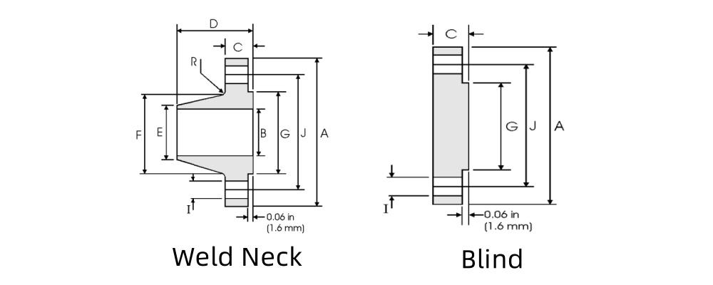
| Nominal P ipe S ize | A | C | D | E | F | G | H | I | J | R | |
| Overall Diameter | WNF Flange Thickness min | Blind Flange Thickness min | Overall Length WNF | Diameter at Weld Bevel | Hub Diameter | Face Diameter | Number of Holes | Bolt Hole Diameter | Diameter of Circle of Holes | Fillet | |
| mm | mm | mm | mm | mm | mm | mm | mm | mm | mm | ||
| 22 | 749.3 | 45.97 | 45.97 | 149.35 | 558.8 | 609.6 | 641.35 | 20 | 35.05 | 692.15 | 9.65 |
| 26 | 869.95 | 68.33 | 68.33 | 120.65 | 660.4 | 676. 15 | 749.3 | 24 | 35.05 | 806.45 | 9.65 |
| 28 | 927.1 | 71.37 | 71.37 | 125.48 | 711.2 | 726.95 | 800.1 | 28 | 35.05 | 863.6 | 11.18 |
| 30 | 984.25 | 74.68 | 74.68 | 136.65 | 762 | 781.05 | 857.25 | 28 | 35.05 | 914.4 | 11.18 |
| 32 | 1060.5 | 81.03 | 81.03 | 144.53 | 812.8 | 831.85 | 914.4 | 28 | 41.15 | 977.9 | 11.18 |
| 34 | 1111.3 | 82.55 | 82.55 | 149.35 | 863.6 | 882.65 | 965.2 | 32 | 41.15 | 1028.7 | 12.70 |
| 36 | 1168.4 | 90.42 | 90.42 | 157.23 | 914.4 | 933.45 | 1022.4 | 32 | 41.15 | 1085.9 | 12.70 |
| 38 | 1238.3 | 87.38 | 87.38 | 157.23 | 965.2 | 990.60 | 1073.2 | 32 | 41.15 | 1149.4 | 12.70 |
| 40 | 1289.1 | 90.42 | 90.42 | 163.58 | 1016 | 1041.4 | 1124.0 | 36 | 41.15 | 1200.2 | 12.70 |
| 42 | 1346.2 | 96.77 | 96.77 | 171.45 | 1066.8 | 1092.2 | 1193.8 | 36 | 41.15 | 1257.3 | 12.70 |
| 44 | 1403.4 | 101.6 | 101.60 | 177.80 | 1117.6 | 1143 | 1244.6 | 40 | 41.15 | 1314.5 | 12.70 |
| 46 | 1454.2 | 103. 12 | 103.12 | 185.67 | 1168.4 | 1196.9 | 1295.4 | 40 | 41.15 | 1365.3 | 12.70 |
| 48 | 1511.3 | 107.95 | 107.95 | 192.02 | 1219.2 | 1247.7 | 1358.9 | 44 | 41.15 | 1422.4 | 12.70 |
ASME B16.47 Series A Class 300 Dimensions
| Nominal P ipe S ize | A | C | D | E | F | G | H | I | J | R | |
| Overall Diameter | WNF Flange Thickness min | Blind Flange Thickness min | Overall Length WNF | Diameter at Weld Bevel | Hub Diameter | Face Diameter | Number of Holes | Bolt Hole Diameter | Diameter of Circle of Holes | Fillet | |
| mm | mm | mm | mm | mm | mm | mm | mm | mm | mm | ||
| 22 | 838.20 | 66.55 | 66.55 | 165.1 | 558.80 | 641.35 | 641.35 | 24 | 41.15 | 742.95 | 9.65 |
| 26 | 971.55 | 79.25 | 84.07 | 184.15 | 660.40 | 720.85 | 749.30 | 28 | 44.45 | 876.30 | 9.65 |
| 28 | 1035.1 | 85.85 | 90.42 | 196.85 | 711.20 | 774.70 | 800.10 | 28 | 44.45 | 939.80 | 11. 18 |
| 30 | 1092.2 | 91.95 | 95.25 | 209.55 | 762.00 | 827.02 | 857.25 | 28 | 47.75 | 996.95 | 11. 18 |
| 32 | 1149.4 | 98.55 | 100.08 | 222.25 | 812.80 | 881.13 | 914.40 | 28 | 50.80 | 1054. 1 | 11. 18 |
| 34 | 120.50 | 101.60 | 104.65 | 231.65 | 863.60 | 936.75 | 965.20 | 28 | 50.80 | 1104.9 | 12.70 |
| 36 | 1270.0 | 104.65 | 111.25 | 241.30 | 914.40 | 990.60 | 1022.40 | 32.00 | 53.85 | 1168.40 | 12.70 |
| 38 | 1168.4 | 107.95 | 107.95 | 180.85 | 965.20 | 993.65 | 1028.70 | 32.00 | 41.15 | 1092.20 | 12.70 |
| 40 | 1238.3 | 114.30 | 114.30 | 193.55 | 1016.00 | 1047.8 | 1085.90 | 32.00 | 44.45 | 1155.70 | 12.70 |
| 42 | 1289.1 | 119.13 | 119.13 | 200.15 | 1066.80 | 1098.6 | 1136.70 | 32.00 | 44.45 | 1206.60 | 12.70 |
| 44 | 1352.6 | 123.95 | 123.95 | 206.25 | 1117.60 | 1149.4 | 1193.80 | 32.00 | 47.75 | 1263.70 | 12.70 |
| 46 | 1416.1 | 128.52 | 128.52 | 215.90 | 1168.40 | 1203.5 | 1244.00 | 28.00 | 50.80 | 1320.80 | 12.70 |
| 48 | 1466.9 | 133.35 | 133.35 | 223.77 | 1219.20 | 1254.3 | 1301.80 | 32.00 | 50.80 | 1371.60 | 12.70 |
ASME B16.47 Series A Class 600 Dimensions
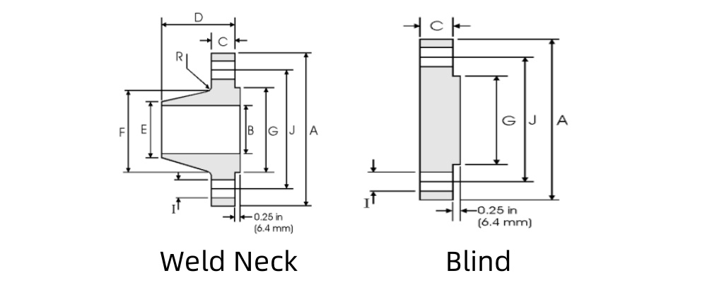
| Nominal P ipe S ize | A | C | D | E | F | G | H | I | J | R | |
| Overall Diameter | WNF Flange Thickness min | Blind Flange Thickness min | Overall Length WNF | Diameter at Weld Bevel | Hub Diameter | Face Diameter | Number of Holes | Bolt Hole Diameter | Diameter of Circle of Holes | Fillet | |
| mm | mm | mm | mm | mm | mm | mm | mm | mm | mm | ||
| 22 | 869.95 | 95.25 | 95.25 | 196.85 | 558.80 | 666.75 | 641.35 | 24 | 47.75 | 777.75 | 11.18 |
| 26 | 1016 | 107.95 | 125.48 | 222.25 | 660.40 | 747.78 | 749.30 | 28 | 50.80 | 914.40 | 12.70 |
| 28 | 1073.2 | 111.25 | 131.83 | 234.95 | 711.20 | 803.15 | 800.10 | 28 | 53.85 | 965.20 | 12.70 |
| 30 | 1130.3 | 114.30 | 139.70 | 247.65 | 762.00 | 862.08 | 857.25 | 28 | 53.85 | 1022.4 | 12.70 |
| 32 | 1193.8 | 117.35 | 147.57 | 260.35 | 812.80 | 917.45 | 914.40 | 28 | 60.45 | 1079.5 | 12.70 |
| 34 | 1244.6 | 120.65 | 153.92 | 269.75 | 863.60 | 973.07 | 965.20 | 28 | 60.45 | 1130.3 | 14.22 |
| 36 | 1314.5 | 123.95 | 162.05 | 282.45 | 914.40 | 1031.75 | 1022.35 | 28 | 66.55 | 1193.0 | 14.22 |
| 38 | 1270.0 | 152.40 | 155.45 | 254.00 | 965.20 | 1022.35 | 1054.10 | 28 | 60.45 | 1162.1 | 14.22 |
| 40 | 1320.8 | 158.75 | 162.05 | 263.65 | 1016.0 | 1073.2 | 1111.3 | 32 | 60.45 | 1212.9 | 14.22 |
| 42 | 1403.4 | 168. 15 | 171.45 | 279.40 | 1066.8 | 1127.3 | 1168.4 | 28 | 66.55 | 1282.7 | 14.22 |
| 44 | 1454.2 | 172.97 | 177.80 | 289.05 | 1117.6 | 1181.1 | 1225.6 | 32 | 66.55 | 1333.5 | 14.22 |
| 46 | 1511.3 | 179.32 | 185.67 | 299.97 | 1168.4 | 1235.0 | 1276.4 | 32 | 66.55 | 1390.7 | 14.22 |
| 48 | 1593.9 | 188.98 | 195.33 | 315.98 | 1219.2 | 1289.1 | 1333.5 | 32 | 73. 15 | 1460.5 | 14.22 |
ASME B16.47 Series A Class 900 Dimensions
| Nominal P ipe S ize | A | C | D | E | F | G | H | I | J | R | |
| Overall Diameter | WNF Flange Thickness min | Blind Flange Thickness min | Overall Length WNF | Diameter at Weld Bevel | Hub Diameter | Face Diameter | Number of Holes | Bolt Hole Diameter | Diameter of Circle of Holes | Fillet | |
| mm | mm | mm | mm | mm | mm | mm | mm | mm | mm | ||
| 26 | 1085.9 | 139.70 | 160.27 | 285.75 | 660.40 | 774.70 | 749.30 | 20 | 73.15 | 952.50 | 11.18 |
| 28 | 1168.4 | 142.75 | 171.45 | 298.45 | 711.20 | 831.85 | 800.10 | 20 | 79.25 | 1022.4 | 12.70 |
| 30 | 1231.9 | 149.35 | 182.37 | 311.15 | 762.00 | 889.00 | 857.25 | 20 | 79.25 | 1085.9 | 12.70 |
| 32 | 1314.5 | 158.75 | 193.55 | 330.20 | 812.80 | 946.15 | 914.40 | 20 | 85.85 | 1155.7 | 12.70 |
| 34 | 1397.0 | 165.10 | 204.72 | 349.25 | 863.60 | 1006.4 | 965.20 | 20 | 91.95 | 1225.6 | 14.22 |
| 36 | 1460.5 | 171.45 | 214.38 | 361.95 | 914.40 | 1063.8 | 1022.4 | 20 | 91.95 | 1289.1 | 14.22 |
| 38 | 1460.5 | 190.50 | 215.90 | 352.55 | 965.20 | 1073.2 | 1098.6 | 20 | 91.95 | 1289.1 | 19.05 |
| 40 | 1511.3 | 196.85 | 223.77 | 363.47 | 1016.00 | 1127.3 | 1162.1 | 24 | 91.95 | 1339.9 | 20.57 |
| 42 | 1562. 1 | 206.25 | 231.65 | 371.35 | 1066.80 | 1176.3 | 1212.9 | 24 | 91.95 | 1390.7 | 20.57 |
| 44 | 1648.0 | 214.38 | 242.82 | 390.65 | 1117.6 | 1235.0 | 1270.0 | 24 | 98.55 | 1463.6 | 22.35 |
| 46 | 1733.6 | 225.55 | 255.52 | 410.97 | 1168.4 | 1292.4 | 1333.5 | 24 | 104.65 | 1536.7 | 22.35 |
| 48 | 1784.4 | 233.43 | 263.65 | 419.10 | 1219.2 | 1343.2 | 1384.3 | 24 | 104.65 | 1587.5 | 23.88 |
Sealing Surface
Raised Face RF
Raised face flanges are the most commonly used flanges in manufacturing plants and are easily identifiable. They are called raised face because the gasket seating surface protrudes above the bolting surface. This sealing surface allows for the use of various types of gaskets, including non-metallic flat gaskets and metal composite gaskets, such as metal wound gaskets and double jacket gaskets.
Full Face FF
The gasket seating surface of a full face flange is the same as the bolting surface. Full-face flanges are typically used in cast flanges. These flanges are primarily used in low-pressure, non-flammable, and non-explosive piping systems.
Ring-joint (RTJ)
Ring-joint flanges are primarily used in high-pressure (Class 600 and above) and/or high-temperature (427°C and above) applications. They feature grooves machined into the sealing surface to accommodate ring-shaped gaskets. When the bolts are tightened, the gasket makes close contact with the inner surface of the groove, forming a metal-to-metal hard seal.
ASME B16.47 Series A Flanges Application
Petroleum and Natural Gas Industry
Natural gas processing equipment
Chemical raw material transportation pipelines
Refining equipment high-temperature and high-pressure systems
Corrosive medium transportation
Electric Power and Energy
Thermal power plant boilers and steam pipelines
Nuclear power plant cooling water and steam systems
Offshore Engineering and Shipbuilding
Large-diameter water supply and heating networks
Industrial circulating cooling water systems