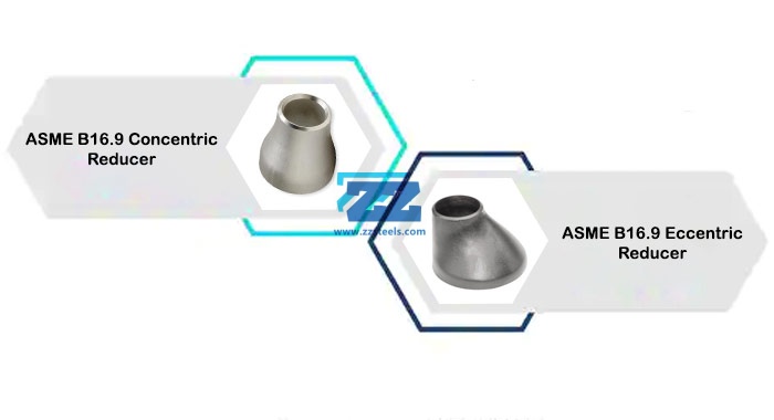
ASME B16.9 butt weld reducers are pipe fittings used to connect pipes of different diameters, serving as size transition components within piping systems. They enable fluid to smoothly transition from one pipe diameter to another, ensuring proper fluid conveyance while minimizing pressure loss.
Reducers typically feature a conical or eccentric conical structure. The conical shape may be concentric, where the center axes coincide, or eccentric, where the center axes do not align. Concentric reducers maintain a consistent centerline when pipe diameters change at both ends, making them suitable for applications with strict fluid flow direction requirements and limited installation space. ASME B16.9 reducers are widely used in pipeline systems across petroleum, chemical, natural gas, power, and metallurgical industries. They connect pipes of differing diameters or facilitate directional changes while conserving space.
Butt Weld Reducers Specification
| Size | Seamless Butt Weld Fittings : 1/2″ – 10″ |
| Welded Butt Weld Fittings : 1/2″ – 48″ | |
| Dimensions | ASME/ANSI B16.9, ASME B16.28, MSS-SP-43, BS4504, BS4504, BS1560, BS10 |
| Thickness | SCH10, SCH20, SCH30, STD SCH40, SCH60, XS, SCH 80, SCH 100, SCH 120, SCH 140, SCH 160, XXS available with NACE MR 01-75 |
| Bending Radius | R=1D, 2D, 3D, 5D, 6D, 8D, 10D |
| Manufacturing process | Push, Press, Forge, Cast, etc. |
| Test Certificates | EN 10204/3.1B |
| Raw Materials Certificate | |
| 100% Radiography Test Report | |
| Third Party Inspection Report, etc |
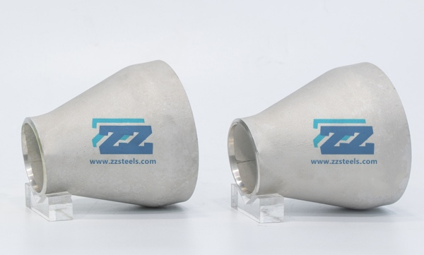
Concentric Reducer
The primary structural feature of concentric reducers is their concentric design. This configuration ensures that the fluid flow direction remains unchanged as it passes through the reducer, maintaining a relatively stable flow state. The defining characteristic of concentric reducers is the perfect alignment of their centerlines at both ends. Viewed from the side, it exhibits a symmetrical conical structure resembling a bell mouth or funnel. This design ensures a smooth transition for the fluid within the pipe, minimizing the generation of vortices and turbulence. This makes it particularly suitable for applications with stringent requirements for fluid flow.
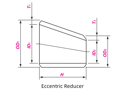
Eccentric Reducer
An eccentric reducer is a pipe fitting used to connect two pipes of different diameters, with its two ends offset from each other. This offset is termed the eccentricity, meaning one side of the fitting is straight while the other tapers gradually at an angle. Unlike symmetrical concentric reducers, the eccentric design aids in controlling fluid flow, reducing turbulence, and preventing gas accumulation or cavitation within the piping system. It is commonly used in applications requiring consistent bottom or top liquid levels in pipelines.
Concentric and Eccentric Reducers
Concentric reducers and eccentric reducers are two common types of pipe fittings used for connecting pipes of different diameters in piping systems. However, due to their structural differences, their respective applications and advantages also vary.
| Feature | Concentric Reducer | Eccentric Reducer |
| Structure | A symmetrical cone with aligned centerlines. | Centerlines are not aligned, with one side flat and the other inclined. |
| Primary Function | To maintain the pipeline’s centerline alignment. | To keep the pipeline’s bottom or top flat. |
| Application | Vertical pipelines, or horizontal pipelines where centerline alignment is required. | Horizontal pipelines, used to prevent liquid or gas accumulation. |
| Advantages | Simple structure, easy to install, lower cost. | Effectively prevents air pockets and liquid accumulation in the pipeline. |
| Disadvantages | Can lead to gas or liquid accumulation in horizontal pipelines. | More complex structure, higher cost, and requires careful orientation during installation. |
ASME B16.9 Seamless and Welded Reducer
Seamless
Seamless reducers are typically manufactured by forming entire lengths of seamless stainless steel pipe through pressure or push forming. The advantage of this process lies in the absence of welds, resulting in higher overall strength and pressure resistance, making it particularly suitable for demanding environments requiring high pressure and temperature endurance. However, due to the use of solid pipe forming, the available size range is relatively limited, and wall thickness control presents greater challenges.
Welded
Welded reducers are produced by rolling stainless steel plates into a conical shape and then welding them together. This manufacturing method offers greater flexibility, making it especially suitable for producing large-diameter or non-standard-sized products, and it is typically more cost-effective. The primary drawback, however, is the presence of weld seams. Although these undergo rigorous inspection, they may be slightly inferior to seamless reducers in terms of pressure resistance and overall strength.
ASTM A403 Concentric Reducer
Chromium (Cr)
Provides the primary corrosion resistance and oxidation resistance; higher content yields better corrosion resistance.
Nickel (Ni)
Enhances material ductility and toughness, improves corrosion resistance, particularly against acidic media.
Molybdenum (Mo)
Significantly enhances resistance to chloride-induced pitting and crevice corrosion (e.g., seawater). Not present in 304.
Manganese (Mn)
Increases solid solution strength and improves machinability.
Silicon (Si)
Enhances oxidation resistance and improves fluidity.
| CHEMICAL | LIMITS | C | Mn | P | S | Si | Ni | Cr | Mo |
| ASTM A403 WP304 | MIN | 8.0 | 18.0 | ||||||
| MAX | 0.08 | 2.00 | 0.045 | 0.030 | 1.00 | 11.0 | 20.0 | ||
| ASTM A403 WP316 | MIN | 10.0 | 16.0 | 2.00 | |||||
| MAX | 0.08 | 2.00 | 0.045 | 0.030 | 1.00 | 14.0 | 18.0 | 3.00 | |
| ASTM A403 WP321 | MIN | 9.00 | 17.00 | ||||||
| MAX | 0.08 | 2.00 | 0.045 | 0.030 | 1.00 | 12.00 | 19.00 | ||
| ASTM A403 WP904L | MIN | 23.00 | 19.00 | 4.000 | |||||
| MAX | 0.02 | 2.00 | 0.045 | 0.035 | 1.00 | 28.00 | 23.00 | 5.000 |
Tensile Strength: The maximum stress a material can withstand before breaking.
Yield Strength: The maximum stress a material can withstand before undergoing permanent plastic deformation.
Elongation: The percentage increase in length of a material at break, reflecting its plasticity and toughness.
| MATERIAL | ASTM A403 WP304 | ASTM A403 WP316 | ASTM A403 WP321 | ASTM A403 WP904L |
| T.S (MPA) | 515 min | 515 min | 515 min | 490 min |
| Y.S (MPA) | 205 min | 205 min | 205 min | 220 min |
| EL % | 28 min | 28 min | 28 min | 28 min |
ASTM A234 WPB Concentric Reducer
Chemical Composition
| CHEMICAL | LIMITS | C | Mn | P | S | Si | Cr | Mo | Ni | Cu | Cb | V |
| ASTM A234 WPB | MIN | 0.29 | 0.10 | |||||||||
| MAX | 0.30 | 1.06 | 0.050 | 0.058 | 0.40 | 0.15 | 0.40 | 0.40 | / | 0.08 |
Mechanical Property
| MATERIAL | T.S (MPA) | Y.S (MPA) | EL % | R/A % | HARDNESS |
| ASTM A234 WPB | 415 min | 240 min | 22 min | 30 min | 197 max |
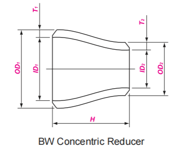
ANSI / ASME B16.9 Reducer Dimensions
Concentric Reducer
| OD1 | OD2 | END TO END | SCH 40 WEIGHT |
| NPS | NPS | H | KG |
| 3/4 | 3/8 – 1/2 | 38 | 0.07 |
| 1 | 1/2 – 3/4 | 51 | 0.14 |
| 1 1/4 | 1/2 – 1 | 51 | 0.19 |
| 1 1/2 | 1/2 – 1 1/4 | 64 | 0.29 |
| 2 | 3/4 – 1 1/2 | 76 | 0.46 |
| 2 1/2 | 1 – 2 | 89 | 0.85 |
| 3 | 1 1/4 – 2 1/2 | 102 | 1.11 |
| 4 | 2 – 3 1/2 | 102 | 1.8 |
| 5 | 2 – 4 | 127 | 3.05 |
| 6 | 2 1/2 – 5 | 140 | 4.35 |
| 8 | 3 1/2 – 6 | 152 | 7.12 |
| 10 | 4 – 8 | 178 | 11.8 |
| 12 | 5 – 10 | 203 | 17.8 |
| 14 | 6 – 12 | 330 | 34.3 |
| 16 | 6 – 14 | 356 | 48.3 |
| 18 | 8 – 16 | 381 | 65.3 |
| 20 | 10 – 18 | 508 | 102 |
| 22 | 12 – 20 | 508 | – |
| 24 | 12 – 22 | 508 | 143 |
| 26 | 12 – 24 | 610 | – |
| 28 | 14 – 26 | 610 | – |
| 30 | 14 – 28 | 610 | – |
| 32 | 20 – 30 | 610 | 230 |
| 34 | 22 – 32 | 610 | 245 |
| 36 | 22 – 34 | 610 | 282 |
| 38 | 24 – 36 | 610 | – |
| 40 | 28 – 38 | 610 | – |
| 42 | 28 – 40 | 610 | – |
| 44 | 32 – 42 | 610 | – |
| 46 | 34 – 44 | 711 | – |
| 48 | 36 – 46 | 711 | – |
| 52 | 40 – 48 | 711 | – |
| 56 | 40 – 52 | 711 | – |
| 60 | 44 – 56 | 711 |
Eccentric Reducer
| OD1 | OD2 | END TO END |
| NPS | NPS | H |
| 3/4 | 3/8 – 1/2 | 38 |
| 1 | 1/2 – 3/4 | 51 |
| 1 1/4 | 1/2 – 1 | 51 |
| 1 1/2 | 1/2 – 1 1/4 | 64 |
| 2 | 3/4 – 1 1/2 | 76 |
| 2 1/2 | 1 – 2 | 89 |
| 3 | 1 1/4 – 2 1/2 | 102 |
| 4 | 2 – 3 1/2 | 102 |
| 5 | 2 – 4 | 127 |
| 6 | 2 1/2 – 5 | 140 |
| 8 | 3 1/2 – 6 | 152 |
| 10 | 4 – 8 | 178 |
| 12 | 5 – 10 | 203 |
| 14 | 6 – 12 | 330 |
| 16 | 6 – 14 | 356 |
| 18 | 8 – 16 | 381 |
| 20 | 10 – 18 | 508 |
| 22 | 12 – 20 | 508 |
| 24 | 12 – 22 | 508 |
| 26 | 12 – 24 | 610 |
| 28 | 14 – 26 | 610 |
| 30 | 14 – 28 | 610 |
| 32 | 20 – 30 | 610 |
| 34 | 22 – 32 | 610 |
| 36 | 22 – 34 | 610 |
| 38 | 24 – 36 | 610 |
| 40 | 28 – 38 | 610 |
| 42 | 28 – 40 | 610 |
| 44 | 32 – 42 | 610 |
| 46 | 34 – 44 | 711 |
| 48 | 36 – 46 | 711 |
| 52 | 40 – 48 | 711 |
| 56 | 40 – 52 | 711 |
| 60 | 44 – 56 | 711 |
Eccentric Reducer Weight
| Eccentric Reducer Weight Chart in kg | |||||||
| Nominal Size | SCH20 | STD | SCH40 | SCH80 | SCH120 | SCH160 | |
| DN | NPS | ||||||
| 15 | 1/2 | 0.08 | 0.08 | 0.1 | |||
| 20 | 3/4 | 0.17 | 0.17 | 0.2 | |||
| 25 | 1 | 0.21 | 0.21 | 0.25 | 0.22 | ||
| 32 | 1 1/4 | 0.29 | 0.29 | 0.35 | |||
| 40 | 1 1/2 | 0.42 | 0.42 | 0.58 | 0.6 | ||
| 50 | 2 | 0.8 | 0.8 | 1.03 | 1.04 | ||
| 65 | 2 1/2 | 1.05 | 1.05 | 1.42 | 1.65 | ||
| 80 | 3 | 136 | 1.36 | 1.9 | |||
| 90 | 3 1/2 | 1.63 | 1.63 | 2.27 | 2.4 | ||
| 100 | 4 | 2.77 | 2.77 | 3.93 | 4.4 | ||
| 125 | 5 | 3.96 | 3.96 | 6 | 7.14 | ||
| 150 | 6 | 6.31 | 6.31 | 9.26 | 10.8 | ||
| 200 | 8 | 7.85 | 10.7 | 10.7 | 17.5 | 15 | 18.4 |
| 250 | 10 | 11.2 | 15.8 | 16.3 | 25.1 | 25.1 | 32.5 |
| 300 | 12 | 25.6 | 28.8 | 32.1 | 56.5 | 41.7 | 53.3 |
| 350 | 14 | 30.5 | 38.5 | 48.8 | 79 | 84.5 | 106 |
| 400 | 16 | 35.2 | 44.5 | 64.3 | 102 | 112 | 143 |
| 450 | 18 | 62.7 | 62.7 | 98.5 | 165 | ||
| 500 | 20 | 72.6 | 72.6 | 181 | |||
| 550 | 22 | 97 | 79.1 | 142 | 226 | ||
| 600 | 24 | 130 | 100 | ||||
Concentric Reducer Weight
| Concentric Reducer Weight Chart | |||||||||
| DN | NPS | 10S | 20 | STD | 40 | XS | 80 | 160 | XXS |
| 20 | 3/4 | 0.1 | / | 0.1 | 0.1 | 0.1 | 0.1 | / | / |
| 25 | 1 | 0.1 | / | 0.2 | 0.2 | 0.2 | 0.2 | / | / |
| 32 | 1 1/4 | 0.1 | / | 0.2 | 0.2 | 0.3 | 0.3 | 0.2 | / |
| 40 | 1 1/2 | 0.2 | / | 0.3 | 0.3 | 0.4 | 0.4 | / | / |
| 50 | 2 | 0.3 | / | 0.4 | 0.4 | 0.6 | 0.6 | 0.6 | 1 |
| 65 | 2 1/2 | 0.5 | / | 0.8 | 0.8 | 1.0 | 1.0 | 1.0 | / |
| 80 | 3 | 0.6 | / | 1.1 | 1.1 | 1.4 | 1.4 | 1.7 | 1 |
| 90 | 3 1/2 | 0.7 | / | 1.4 | 1.4 | 1.9 | 1.9 | / | / |
| 100 | 4 | 0.8 | / | 1.6 | 1.6 | 2.3 | 2.3 | 2.4 | / |
| 125 | 5 | 1.4 | / | 2.81 | 2.8 | 4.0 | 3.9 | 4.4 | / |
| 150 | 6 | 1.9 | / | 4.0 | 4.0 | 6.0 | 6.0 | 7.1 | 8.6 |
| 200 | 8 | 2.8 | / | 6.3 | 6.3 | 6.0 | 9.3 | 10.8 | 12.6 |
| 250 | 10 | 4.6 | 7.9 | 10.7 | 10.7 | 9.3 | 17.5 | 18.4 | 17.9 |
| 300 | 12 | 7.0 | 11.2 | 15.8 | 16.3 | 14.5 | 25.1 | 32.5 | 29.3 |
| 350 | 14 | 14.0 | 25.6 | 28.8 | 32.1 | 21.0 | 56.5 | 53.3 | 41.7 |
| 400 | 16 | 17.5 | 30.5 | 38.5 | 48.8 | 37.1 | 79 | 106.0 | / |
| 450 | 18 | 21.5 | 35.2 | 44.5 | 64.3 | 48.8 | 102 | 143.0 | / |
| 500 | 20 | 36.0 | 62.7 | 62.7 | 98.5 | 58.5 | 165 | / | / |
| 550 | 22 | 38.0 | 72.6 | 72.6 | / | 80.4 | 181 | / | / |
| 600 | 24 | 47.5 | 97.0 | 79.1 | 142.0 | 93.8 | 226 | / | / |
How to Calculate The Weight of Steel Pipe Reducer?
0.02466 × S ×[ (D+d)/2-S] × H / 1000
S: Wall thickness of Butt Weld Reducer
D: Outside diameter of the larger end
d: Outside diameter of the small end
H: End to end dimension
ASME B16.9 Standard
This Standard covers overall dimensions, tolerances, ratings, testing, and markings for factory-made wrought buttwelding fittings in sizes NPS 1/2 through NPS 48 (DN 15 through DN 1200).
Pressure Rating Designation
Class followed by a dimensionless number is the designation for pressure-temperature ratings. Standardized designations for flanges per ASME B16.5 referenced in this Standard are Classes 150, 300, 600, 900, 1500, and 2500.
Marking
Standard Marking Each fitting shall be permanently marked to show the following:
(a) manufacturer’s name or trademark
(b) material identification, either the ASTM or ASME grade designation
(c) schedule number1 or nominal wall thickness in mm
(d) size — the nominal pipe size (NPS) identification number related to the end connections shall be used
(e) compliance—see para. 4.4 for standard and special fitting marking
A manufacturer may supplement these mandatory markings with others, including a DN size designation, but confusion with the required marking shall be avoided.
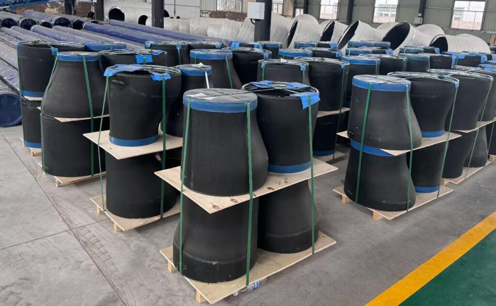
Packaging
For large-sized or heavy carbon steel pipe reducers, individual packaging or bundling may not provide sufficient support. Therefore, they are typically stacked neatly on large wooden pallets. The wooden pallet provides a sturdy base platform that evenly distributes weight, preventing deformation of the pipe fittings due to uneven stress. Subsequently, forklifts can directly lift the pallets from the bottom, significantly improving loading/unloading efficiency while reducing damage risks associated with manual handling. Fittings of the same specification or batch are grouped together on a single pallet for easier inventory management. Before packaging, plastic pipe caps are installed on both ends of the fittings or they are wrapped with plastic sheeting to protect the beveled edges and inner walls from scratches and prevent dust or moisture ingress.
During packaging, the large and small ends are securely strapped to wooden pallets using steel or nylon strapping to prevent shifting or tipping during transit. This method is particularly suitable for long-distance shipping or export, offering superior protection against damage.
To learn more about carbon steel pipe reducers, please click
Advantages
Integrally formed with no welded seams, eliminating risks associated with welding defects.
High strength and superior pressure resistance, suitable for demanding operating conditions.
Smooth inner walls with natural transitions minimize turbulence and pressure loss.
Excellent corrosion resistance, commonly manufactured from stainless steel grades such as 304/316L.
Widely applied in petroleum and natural gas, chemical, power generation, offshore engineering, and pharmaceutical industries.
Application
Oil and gas pipeline systems
Chemical and petrochemical plants
Power and nuclear power plant pipelines
Marine engineering and shipbuilding
Pharmaceutical and food processing industries
Water treatment and environmental engineering
Heating and air conditioning (HVAC) systems
Industrial piping for high-pressure, high-temperature, and corrosive media
ASME B16.9 Reducers Manufacturers & Supplier
We are a professional reducer manufacturer, offering high-quality stainless steel, carbon steel, and alloy steel reducers, including concentric reducers and eccentric reducers. Additionally, we produce various butt weld fittings and forged fittings, manufactured strictly in accordance with international standards such as ASME, ANSI, DIN, EN, and GB to ensure dimensional accuracy and reliable performance. Our pipe fittings are widely used in industries such as oil and gas, chemical, power generation, marine, and pharmaceutical, meeting diverse pipeline connection requirements across various operating conditions. Leveraging premium materials, advanced production techniques, and stringent quality control, we provide comprehensive pipe fitting solutions—including reducers, tees, elbows, reducers, and custom fittings—empowering customers to build safe and efficient pipeline systems.
Exported Countries
We Export Reducer to Saudi Arabia, United Arab Emirates, Qatar, Bahrain, Oman, Kuwait, Jordan, Cyprus, Singapore, Malaysia, Indonesia, Thailand, Vietnam, South Korea, Japan, Sri Lanka, Maldives, Bangladesh, Cambodia, Argentina, Bolivia, Brazil, Venezuela, Colombia, Ecuador, Guyana, Paraguay, Uruguay, United States Of America, Canada, Mexico, Panama, Jamaica, Bahamas, Denmark, Norway, Germany, France,Italy, United Kingdom, Spain, Belgium, Greece, Czech Republic, Portugal, Hungary, Albania, Austria, Finland, Ireland, Croatia, Malta, Nigeria, Algeria, Angola, South Africa, Egypt, Europe, Africa, Asia, North America, South America, Middle East.etc,Italy, United Kingdom, Spain, Belgium, Greece, Czech Republic, Portugal, Hungary, Albania, Austria, Finland, Ireland, Croatia, Malta, Nigeria, Algeria, Angola, South Africa, Egypt, Europe, Africa, Asia, North America, South America, Middle East.etc